Details of Practical Mining
McGraw-Hill, London 1916
Prospecting Headframe with Automatic Dump (By Charles Mentsel)
A little consideration of the stresses in a headframe and a few minutes calculation will show
that a frame of good design and sufficient strength and stability for sinking purposes can
be constructed at considerably [pg.292] less cost than the four-post frame, cross-braced on
all sides, so often found over a prospecting shaft. In addition, the greater convenience,
decrease in surface attendance and greater speed in handling buckets, owing to the self-dumping
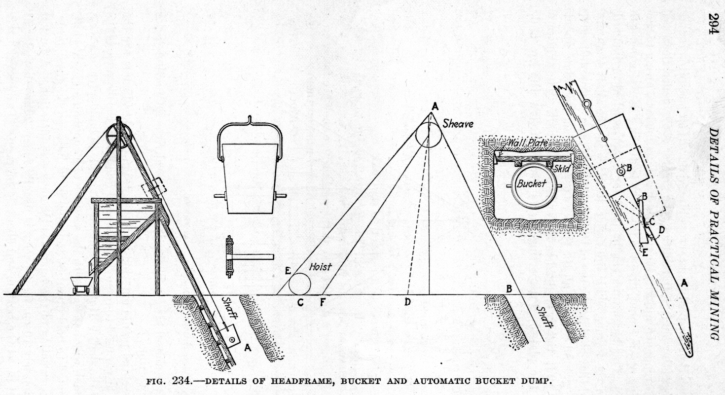
arrangement, give the type illustrated in Fig. 234 decided advantage.
This headframe can be used for either vertical or inclined shafts. In the former, skids are
easier to place in the shaft than are guides, and they obviate the use of the crosshead, often
a source of danger. Where the ground is good, all the timber necessary is a wall plate about every
8 or 10 ft. tightly wedged to the ends of the shaft. The skids are spiked to the plates. Prospecting
shafts usually follow the ore and, [fig. 233] therefore, are almost always inclined; and generally
the inclination varies from time to time.
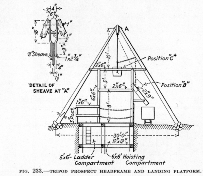
The essential points entering into the design of a headframe are the height of the car used to remove
the hoisted muck, and the distance of the hoist from the shaft. If it is considered advisable to
build a frame with a pocket, which will do away with the services of a top man on night shift,
it is calculated to hold about 30 tons and to fit between the front posts.
The construction of the bucket is the next consideration. A bucket of approximately 10 cu. ft. capacity
is usually about 28 in. diameter at the top, 24 in. at the bottom and about 34 in. deep. Two horns, 8 or 9 in.
long and 1 1/4 in. in diameter, are fastened to opposite sides of the [pg.293] bucket about 9 or 10 in. from
the bottom, as shown. They are attached to flanges riveted inside and outride the bucket as shown in detail
below the view of the bucket itself.
The position of the sheave depends upon the height of the dumping device and the amount of overwind allowable.
In prospecting shafts the danger of overwinding is small with the slow, low-power, geared hoists usually
employed, so 5 ft. is sufficient, and taking the length of bale, clevis, thimble and about 2 ft. of cable
doubled to clamp it, gives about 10 or 12 ft. as the distance from the dump to the tangent point of the
sheave wheel. Knowing the diameter of the sheave and the size of the pillow blocks, the vertical posts can be
readily located. Having the front posts, the back braces may be drawn as follows: Scale off the distance of
the hoist from the collar as shown in the diagram. Draw AE tangent to hoist drum and sheave. Theoretically the
line AD bisecting the angle EAB is in the best position to receive the pull of the hoist and the resisting pull of
the load. AD, however, may be too close to the line of the vertical posts to ensure stability, and it is better
in any event to place it so that the foot comes closer to the hoist at F. The positions of the posts and
back braces have now been decided. To find out how to place these with respect to the draft we must consider
how the bucket rides on the skids. This is shown in the plan of the shaft, and in the elevation of the headframe
and at A. The skids are 6- or 8-in. round skinned poles dressed at the parts where they are fastened to the wall
plates and are placed so that the bucket rides on them as shown, without touching the wall plates. The horns
do not come into contact with anything in the shaft. With this sketch made we have the position of the hoisting
cable with respect to the shaft and headframe, and can locate the posts and back braces.
The posts are tied with three girts and a cap, and the back braces with two girts. The batter may be 1:8 or 1:10,
depending on the rise of the shaft. For a foundation, ordinary log cribwork is built up and filled with waste
rock and the stringers spiked to the cribbing with drift bolts. In one frame 10 X 10-in. hewed timber was used and
1-in. tie rods and bolts, and 8 X 8-in. timber for the bin. A smaller frame was con¬structed of 8 X 8-in. timber
and ¾-in. tie rods. The front posts are set at the inclination of the shaft and are connected with the back braces
by means of girts and tie rods.
The shaft skids run from the shaft to the point of dump. The dumping skids of 8 X 8-in. timber begin about 6 ft.
below the dump and are bolted to the headframe. As the bucket is hoisted out of the shaft, the horns ride on the
runners on the dumping skids, which are placed so that the distance between the inner faces is an inch or two
greater than the width of the bucket, to allow clearance. The shaft skids prevent [pg. 295] the bucket from tipping
on the horns at this point. The bucket continues up the dumping skids until the horns drop into a dap on each skid.
At this point the hoist is stopped and the bucket allowed to swing by gravity, thus dumping. The bucket is now raised a
foot or so and then lowered. In lowering, the horns engage trippers which are thrown over the daps, allowing the horns
to slide down without catching in the daps. The trippers then swing back by gravity leaving the daps free to hold the
horns of the bucket on the next trip.
The dumping device is simple and can be made by any mine black¬smith. The construction is shown on the right of Fig. 234.
The tripper E is shown in full lines in its normal position. When the horn B engages it on its down trip it carries it with
it until it is stopped by the catch D. This enables the horn to go past the dap C without bring stopped by it, as shown by
the dotted lines. After the bucket has passed, the tripper swings back to its first position by gravity, since the lower
part of the [pg.296] tripper is made heavier than the upper. The runner A with the dap C, which should be at least 2 in.
deep, is made of 3/8 X 2-in. iron bolted flush with the timber. The tripper is best made of 5/8 X 3-in. iron mid about
20 in. long and should swing from a 1-in. bolt. The construction is ap¬parent. A headframe of this description can be
built at a cost of about $50 for a small one and $150 for a larger one, including all material and labor. Any carpenter
of ordinary ingenuity should have no trouble in designing and framing it. For vertical shafts the same form can be used,
carrying the skids up mid bending them at the collar to meet the frame at the dump. A few saw cuts on the inside of a
green pole make it possible to bend it through a considerable angle without breaking. Of course, a roller for the cable
is required at the shaft collar in this case.
Substitute for Small Headframe (By Walter R. Hodge).—The type of head rigging shown in Fig. 235 has been used in many
places on the Mesabi range in sinking test pits and shallow timber shafts. It would be useful in most places where a
temporary headframe is needed for shallow depths. It consists of two pieces of round timber about 28 ft. long,
supported a little more than half way toward the small end by a roughly made bent slightly inclined. The large
end is weighted with waste rock or timber. The two timbers are set dose together and the sheave revolves between
them. The sheave is retained in place by two collars or simply revolves between two heavy pegs driven in the logs.
Such a device may do good work to a depth of 200 ft. A small “puffer” is usually the source of power on the Mesabi.
A windlass may be framed to the butts of the timbers and leave the collar of the shaft free from obstructions.
TURN SHEAVES
Turn-sheave Types (By Floyd L. Burr).—In any turn-sheave frame whatever, the sheave wheel will be supported by a
pair of members whose axes lie in planes parallel to the plane of the sheave. Generally also the plane containing
these two axes will be at right angles to die plane of the sheave. These members will usually at their ends frame
into maiin supports which are vertical, horisontal or at right angles to the sheave supports. Four types of turn-sheave
or angle-sheave frame may be recognized.
Type No. 1.—When the line of the resultant of the two ropes is steep and either upward or downward, the principal part
of the frame may take the form of a pair of members parallel to the resultant reaching upward into the air from a
concrete or other base. The sheave is at¬tached to these members and the stress, tension or compression depending
upon the direction of the resultant, is transmitted to the concrete base, which by virtue of its weight resists
the lifting tendency or by its stiffness spreads the compression over a sufficient area of die soil beneath, while
by end bearing and skin friction it resists the tendency to slide hori¬zontally. The tension or compression members
may be of steel or wood.
Type No. 2.—When the line of the resultant is comparatively flat, the frame may consist essentially of a pair of
strut-beam members parallel to the resultant, framed between two piers or towers, one or both of which will tend
to overturn in a longitudinal direction when the rope is stressed. The piers or towers may be of steel or wood or
concrete or reinforced concrete, while the strut-beam may be of wood, steel or rein¬forced concrete. The towers or
piers may, as a variation in design, get some of their stability from diagonal tendon or compression braces reaching
to the ground or to auxiliary piers or natural anchorages.
Type No. 3.—The same sort of a structure as that mentioned for type 2 may be set with the supporting-beam members
normal to the resultant. In this case the resultant load subjects the members to the bending stress only, and tends to overturn the towers
in a transverse direction. [pg.297]